
This article shows a step by step process of restoring your G503 WWII Jeep Engine 6 volt Autolite Generator


|
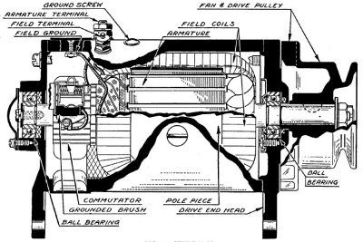
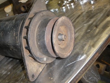
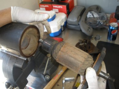
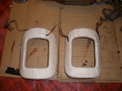
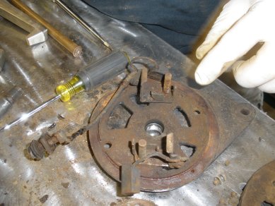
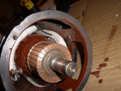
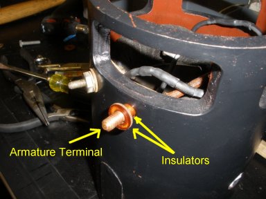
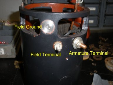
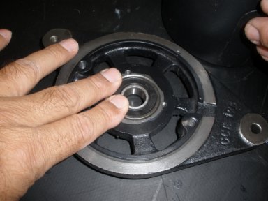
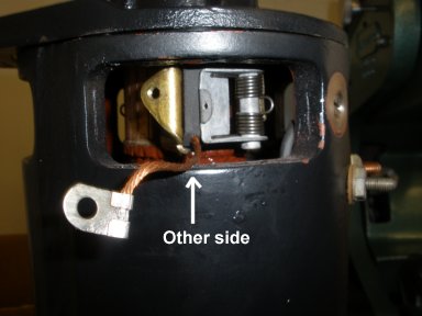
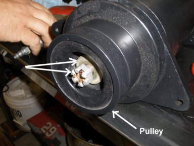
1. Note: there are primarily 4 different types of 6v WWII jeep generators. (Early 41-42 MBs) with two oilers (front/back) (Early 42 GPWs) with ball bearings (front/back) (43-45) with sealed bearing fron and oiler back Finding the correct kit may take a combination of kits. First, Let's get familar with some of the components as shown here. |
|
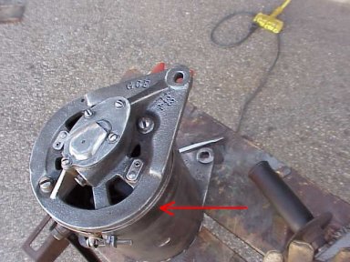
2. Remove cover band so you can get to the rear cover plate Brush Leads. Special thanks to Harley Padilla who has the knowledge and equipment to make this article possible. |
|
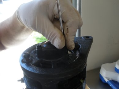
3. Remove the commutator cover plate screws from the back cover plate of the generator. |
|
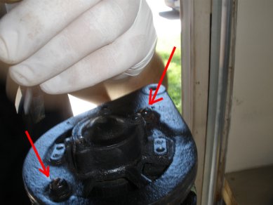
4. Remove the rear cover plate long bolts. These might be a little tight, but usually will break free with your torque of a large screw driver. |
|
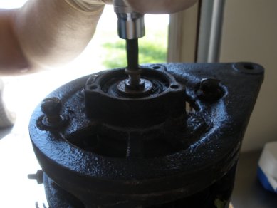
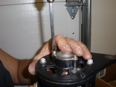
5. Remove the center screw from the end of the commutator end cover plate. Note: the cover plate is still connected via wiring on the inside, so don't try and pull it off yet. |
|
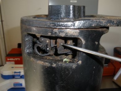
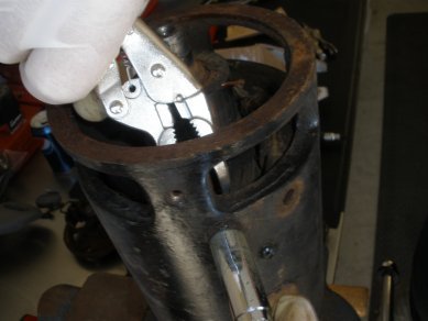
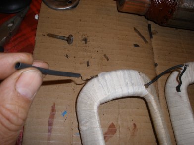
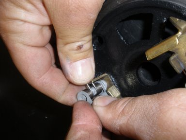
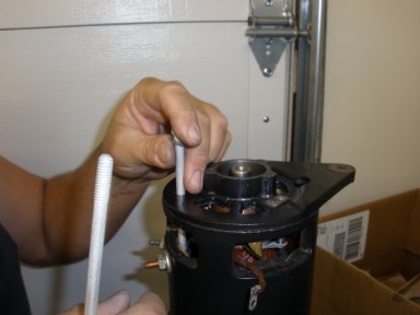
6. Next, we want to disconnect the brushes. Find a hook type device that will allow you to pull back the brush springs as shown here. |
|
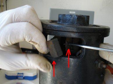
7. Next, remove the brushes by pulling back the brush springs, and lightly tugging on the brushes. You have to open up the brush spring covers in order to easily pop the brushes out. |
|
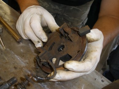
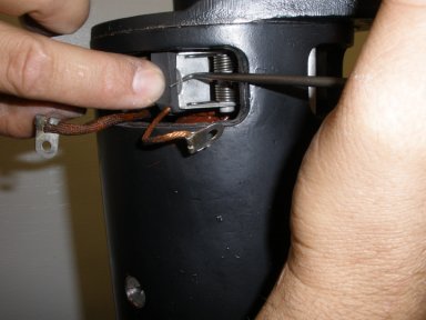
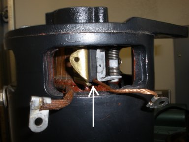
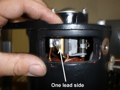
8. With the brushes disconntected, carefully open the faceplate so you can see the terminal connections inside the core casing. |
|
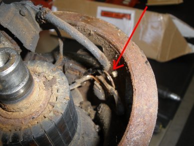
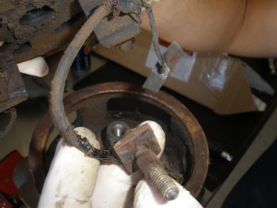
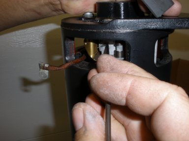
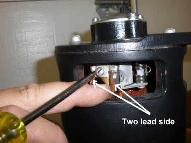
9. Disconnect the terminals from the casing. There are three connections that you will need to disconnect, so take your time and carefully disconnect each of them as the wires are brittle. |
|
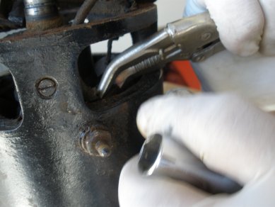
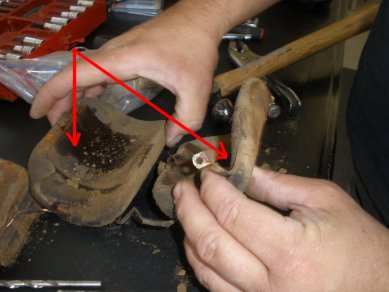
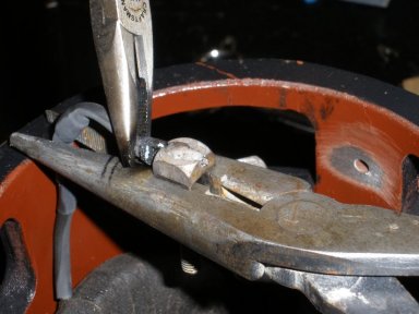
10. The terminals are a little difficult to get to, but you can hold one side with needle nose pliers and the other use a socket to remove the terminal nuts. Pop the terminals through to the inside. |
|
11. With the terminals and ground disconnected and the brushes out from their springs the cover plate is ready to come off. |
|
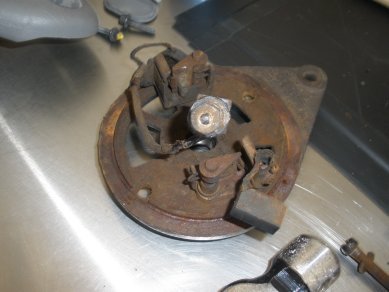
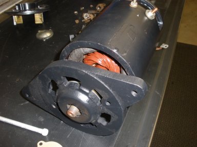
12. Back cover plate is now off the backside of the generator housing. |
|
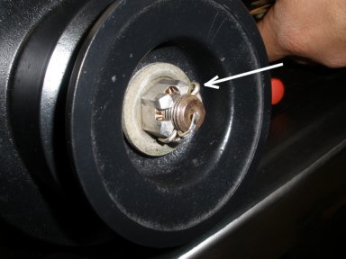
13. Now move the front part of the generator housing. Remove Shaft nut, Plain washer, and Lock washer |
|
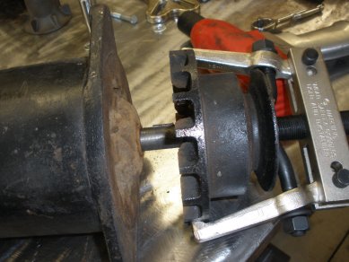
14. Use a puller to pull off the front pulley as shown. |
|
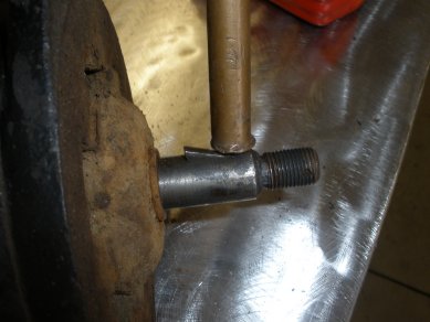
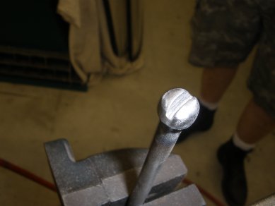
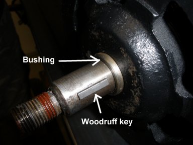
15. Remove Woodruff key by tapping one end (to pop up the other) and pull off |
|
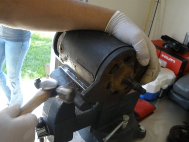
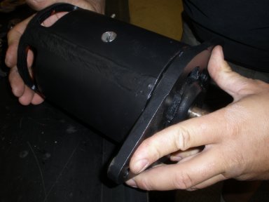
16. Now tap the head cover from the casing, and the cover should pop off. |
|
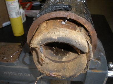
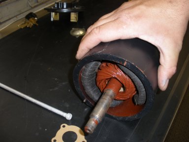
17. With the front and back covers off the housing, the commutator should pull right out. |
|
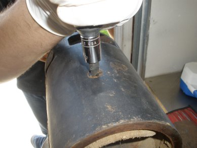
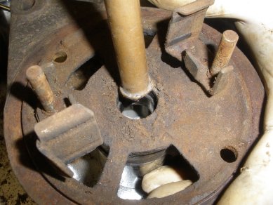
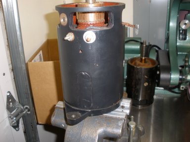
18. To get the field coils out, we need to use an impact wrench with a slotted end. You may need to apply a little heat and/or penetrating oil to have these brake loose. These are very stubborn to remove. |
|
19. With the field coils two screws removed from the housing, gentley remove the field coils by pulling them out. Note: they are connected together. Be careful not to break the connection when pulling the field coils out. |
|
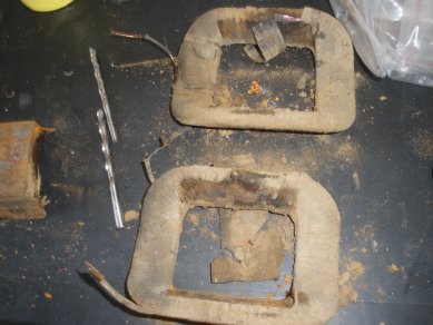
20. The field coils have a couple of heavy metal plates that are in the center of the field coils. You want to push those out of the center area and clean them up. |
|
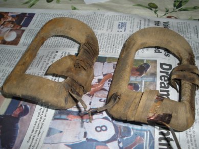
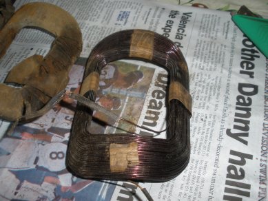
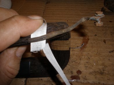
21. Field Coils many times rebuilders ignore the field coils. After 60 years, its time for a fresh cloth taping. Here you see the two field coils still attached by a wire connteciton. Since the tape is practically falling off it should be replaced. You will need cloth tape handy. |
|
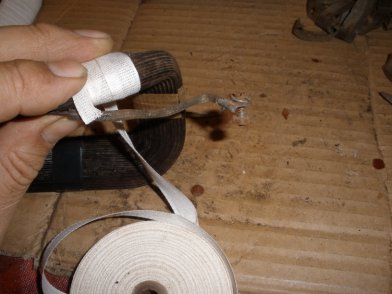
22. Placed on newspaper because it will be a little messy, seperate the field coils carefully. Want to be careful to keep not tear up the fragile wires. |
|
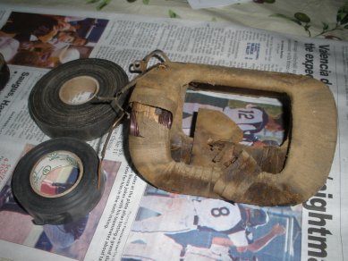
23. Prepare your work area by having a good roll of cloth tape. Note: if your rolls are too large you will not be able to wrap around the field coils with one piece. |
|
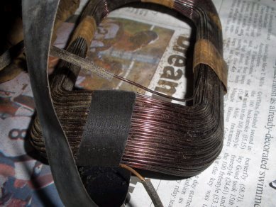
24. Unravel the tape carefully. The coils are held in place by four strands of a cloth tape that will most likely come apart as you are unraveling. You don't want the coils to fall apart, so have your cloth tape ready to replace. |
|
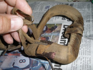
25. Here you see the tape is off and the four places that the paper is holding coils together. We will replace these with cloth tape. Very important not to let the coils fall out of place, AND DO NOT make these too thick, just enought ot hold together. If you make these thick, you will have problems with the commutator rotating. |
|
26. With the cast and casing parts cleared, now you want to blast and clean them up. These pieces were very dirty, so a little wire brushing and sand blasting cleaned them up well. |
|
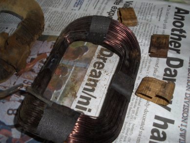
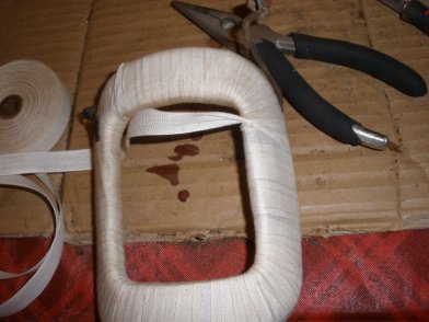
27. Tear a piece of Cloth tape, enough to wrap it twice around the coils. Carefully, wrap tightly around the coils. Note the position of the connecting wires as you want them to be in the same exact place as they were before. |
|
28. Repeat these steps for all four connections where the paper holder were located. Be careful to keep the coils in place. |
|
29. Now start wrapping the coils with the cloth tape. Again note the position of the wires so that you tape it up the same way they were before. |
|
30. Continue taping around the coils (Do Not make it too thick!). Note the overlapping width from the other coil and try and duplicate the same overlapping distance as they were originally. |
|
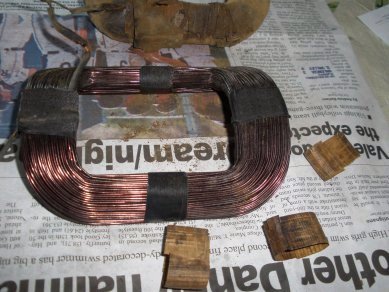
31. First coil completed and wrapped well. Looks good. |
|
32. Note the connecting wires position. You want to make sure that you get under and over these wires as they were prior. |
|
33. Now repeat the same steps on the other coil. Start with unwrapping, and replacing the four point paper wrap with cloth tape. |

|
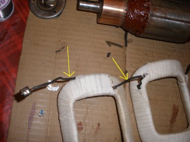
34. Field Coils now completed. They look good and you know they will last another 60 years or more. |
|
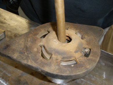
35. Remove Bearings Now we move back over to the housing covers which hold the bearings. Start with the pulley side cover plate. Here we place the cove over an over sided cylinder. Take a tap, and tap the bearing out of the center of the cover plate. |
|
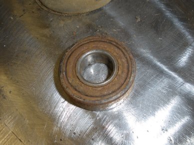
36. The bearing will pop right out. These bearings can be replaced from your local Napa Auto store for about $11 each. (you will need two of them) |
|
37. On the back plate, we need to remove the wiring that we left on from earlier. |
|
38. Disconnect all of the wiring on the back cover (anything with screws) leave the riveted terminals on the back. |
|
39. With all the wires disconnected from the rear plate, we can pop the bearings out of the center of the plate as we did with the front cover, that is, with a punch and tap it out. |
|
40. Both bearing removed, we can now send our housing out for sandblasting and start cleaning the pieces in anticipation of putting it back together. |
|
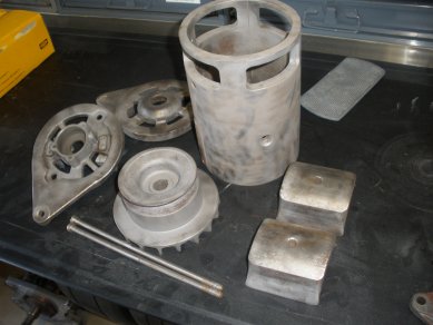
41. All parts that can be sandblasted are completed. Next we are going to fix some of the areas that need restoring. |
|
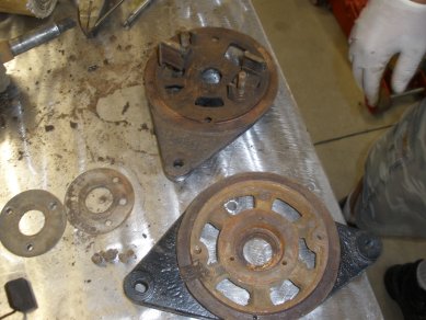
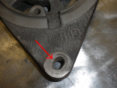
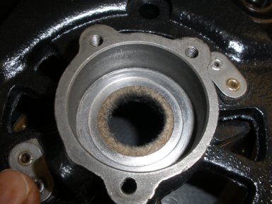
42. Here we are going to try and fix the generator face plate holes. Both the front and back holes have been expanded over time. In many cases, welds do not stick to cast iron..but we are going to try. |
|
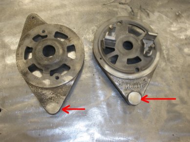
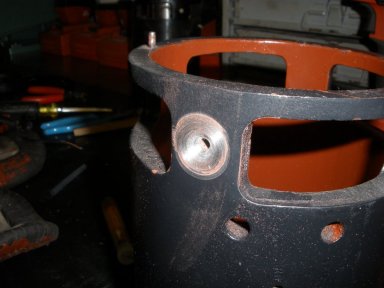
43. In our 220 welder we have a good hard steel, so it looks like the welds will stick. We filled both the holes via welder and grinding them down. We will center the position and drill a new 5/16in hole. |
|
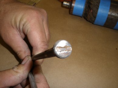
44. In addition, one of our long bolts need the head fixed up, so we will fill the head with a weld and cut out a new slot. |
|
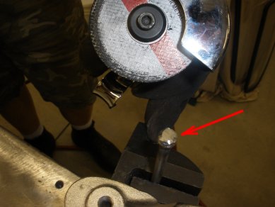
45. Here you see the head is filled with a weld and grounded to its original shape, and we prepare to create a new slot with and angle grinder. |
|
46. Nice new head on the long generator bolt is looking good. Ready for both bolts to be re-plated. |
|
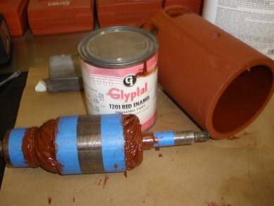
47. Next, we primered the generator casing, and now we are going to insulate the commutator wiring and the inside of the generator casing wall. We use the popular, but hard to get in California "Glyptal" insulating red enamel. This insulator is to help water proof your generator wiring. |
|
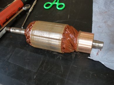
48. With the commutator insulating paint dried, we remove the painters tape. We hit the commutator with a little sand paper to help clean up the brass area where the brushes will ride, and the center section where the field coils are represented. |
|
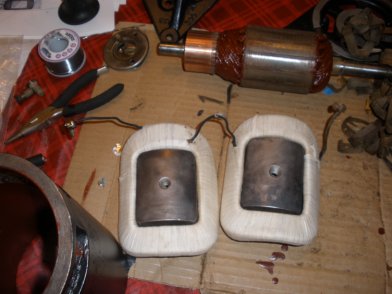
49. With the field coils taped, we place the cleaned field coil blocks into place. We removed the brittle insulator on the wires from the coils and will replace with new shrink wrap insulation. |
|
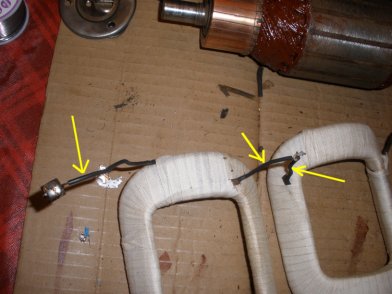
50. At this point we need to prepare the field coil wires to be re-installed. In this case, the wire insulation has crumbled and the the wire between the field coils has broke. So we need to fix these items. |
|
51. The first thing we want to do is to insulate the wiring again. Here we are preparing some Heat Shrink wraps around the wire. We measured the wrap and cut it slightly shorter than the end of the wires. |
|
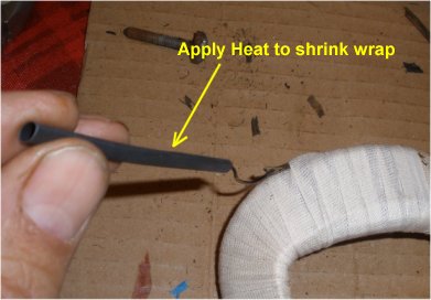
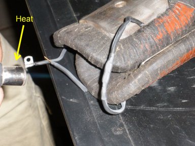
52. Next, we used a micro torch to quickly heat the wrap around the wire. Because the original wrap was faily thick, we used two shrink wraps around each wire by repeating this step. |
|
53. Now the wires are well insulated and we can look to repair the broken wire between the two field coils. |
|
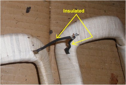
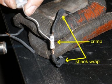
54. Here we repaired the broken wire between the field coils. We used a crimp first, then soldered it together. NOTE: we prepared the shrink wrap before we crimped the wire and soldered. Also, let the solder cool down before trying to apply shrink wrap |
|
55. Here we show the 2nd shrink wrap over the crimp and we applied heat with a micro torch. The field coils are now connected back together and insulated. |
|
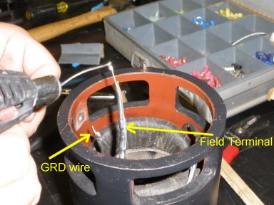
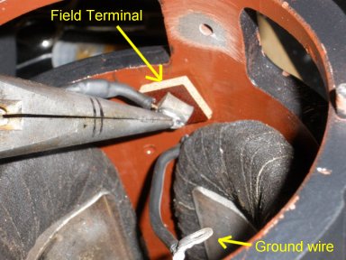
56. Here you see we dropped the field coils into the housing to see how much wire we had to work with on the Field Terminal. The Ground wire did not need repair so we are ok, but the field terminal needs to be reconnected. Here we prep the wire with some solder. |
|
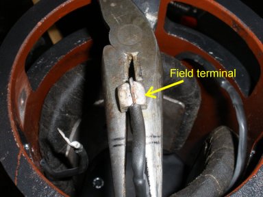
57. We prepared a new NOS field terminal head with solder, and now will zap the terminal head with heat and drop the wire into the field terminal head. |
|
58. Nice, the field terminal head soldered up nicely. Now all the connectors are ready to be routed into the housing after we crank down the field coils to the housing. |
|
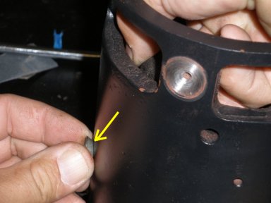
59. Prior to putting in your field coils, clear the paint around the ground plug, inside and out. If you don't have a good ground, your generator is not going to work. Here, we cleaned the pain around the Ground screw area. We will touch up with paint later. |
|
60. Here you see Harley applying new NOS screws to the outside of the generator housing. We had to drill these out earlier. You must really crank these down in order for your armature to be able to turn. |
|
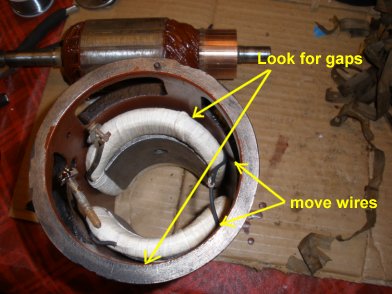
61. After we tighten on the field coils with the screws, we want to look for gaps to the housing. If you can see through to the other side, your field coils are not on tight enough. for the last turn, we used an impact wrench to help get it on tight enough. |
|
62. To test that we have the field coils on tight enough, we insert the commutator into the field coils. The first time we did this it was too tight. Then we cranked down the field coils screws some more, then it would turn freely. With the new taping, we expect it to be very tight. |
|
63. Now we are ready to install the field terminal into its slot on housing. Install the square (or circlular) insulator on the back side and insert into the hole labeled Field on outside of housing. |
|
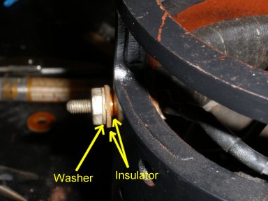
64. After inserting the field terminal through housing, install the cylinder insulator and circular insulator around the bolt, then washer and nut as shown. Tighten down, BUT NOT too tight! just enough to hold firmly against housing. |
|
65. Now take the seperate Armature terminal with insulator and place it through the housing as shown. Note all the other connections around. |
|
66. Install the insulators on the outside of the Armature Terminal as shown. |
|
67. Tighten the armature washer and nut down firmly to the housing. Again, be careful not to tighten down too tight. |
|
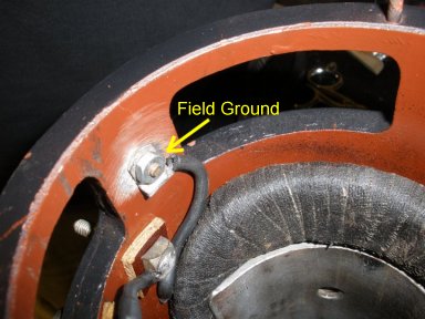
68. Now insert the flat head field ground screw into the outside of housing and tighten up on the inside. Here you see we have a good ground source. |
|
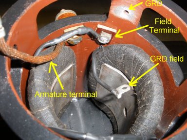
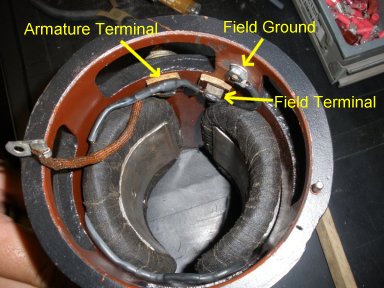
69. Now that everything is tightened up lets review... Both Armature and Field terminals are connected, and field ground is connected as well. |
|
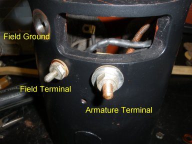
70. From the outside of the housing, your see Armature and Field terminals and field ground |

|
71. Note about Generator wire. The Terminals and Field coil wires can be very brittle, you can replace this with insulated 10 Gage Copper wire from the Restoration Stuff. |
|
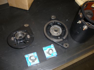
71. Now get your end plates, bearings, and housing to prepare to complete the reassembly. |
|
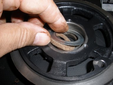
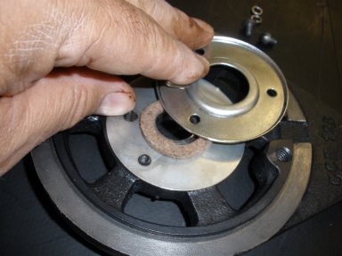
72. On each end of the plates, install the felt washer and reatainer ring. |
|
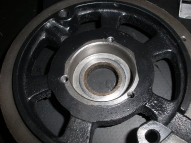
73. Lets start with the Drive End Plate, Place the felt washer in first around the center hole, and tap your retainer ring into position, when the retainer ring is secure, you should see the felt washer through the center of the plate as shown. |
|
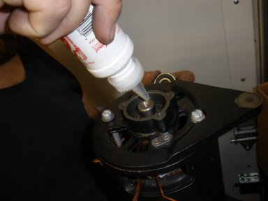
74. Next, install your bearings over the retainer ring. It should be a little snug, and you can tap it in gently if needed. If really tight, then apply a little assembly lube around the surface of bearing and tap in. |
|
75. To complete the Drive End Plate, install the next felt washer and bearing retainer plate as shown |
|
76. Screw in the bearing retainer plate. The NOS kits have these screws included with the kit. |
|
77. Now, install the felt washer and retainer ring the same way in the Commutator End Head Plate as shown. |
|
78. Now install the Commutator into the housing for preparation of installing the Drive End plate. |
|
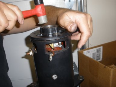
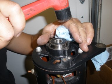
79. After the Commutator is in the housing, Place the Drive End plate over the Commutator shaft. It will be snug, apply some assembly lube if needed to slide it on. Line up the holes in plate with the shafts sticking out of the housing and tap on tight. |
|
80. As you can see pushing the plate on can be a little challenging. With all the fresh paint it goes on tight. You have to press this on tight. |
|
81. When you get the bottom plate on, turn the housing over on a vise so you can install the Commutator End Head Plate as shown. |
|
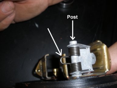
82. Replace the End Plate brush Springs. The NOS kits come with new springs and it is recommended to replace them. The springs can really only go on one way and the key is to look at the clip at the rear. |
|
83. Here you see how the clip needs to fit on the post. |
|
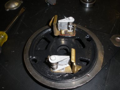
84. Here both brush assembly springs are installed. |
|
85. Now, install the Commutator End Head plate on to the housing. Like the other plate, this should line up with the studs out of the housing and will most likely be a little snug. Tap on if needed for a tight fit. |
|
86. Now install the Through Bolts with lock washers into the housing. Becarefull not to rip into your wiring as you line these bolts up. You may need to move the wiring around on the inside of the generator. |
|
87. Now install the new brushes. Pull back the spring assembly with a hook pick thus allowing you to slip the new brushes in. |
|
88. With the spring pulled back with the hook pick, slide the brush into position. The brushes can only go in one way correctly, and with the wire in the down position it should slide in very easily. When you let the spring back, it will snap into place. |
|
89. Here you can see one of the two brushes are snuggly in place. You want to repeat the same steps for the other side as well. |
|
90. Flipping over to the other side and repeating the steps you see this side is a snug fit as well. |
|
91. Now prepare the Commutator shaft with a little assembly lube so the bearings will slide on easily. |
|
92. Tap the Bearings on easily. You don't want to ruin the bearing with a huge blow, so lightly tap them into position in the End Plate. |
|
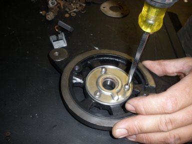
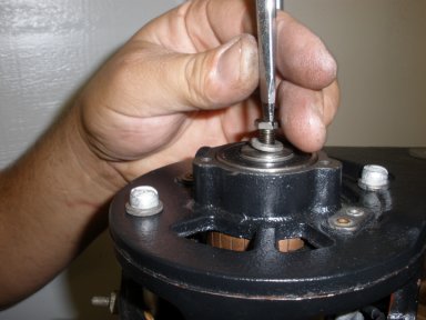
93. Almost done with this end. Install the Retainiing washer and retainer screw into the commutator shaft |
|
94. Install the cover gasket and cover plate as shown and you are complete with this end. The NOS kits have a nice plated cover plate that cleans up well from the cosmoline. |
|
95. Now attach the brush leads to the spring assemblies. Starting with the side that only has one wire from the brush, attach it to the spring assembly as shown. These screws are included in the NOS kits. |
|
96. Now attach the Terminal Lead and the Brush Lead on the other side to the Spring assembly as shown. Note the position of how to screw the ends on (away from each other) |
|
97. Now flip the generator over and install the bushing and woodruff key onto the commutator shaft as shown. |
|
98. Slide the pulley over the shaft and install the shaft lock washer and castle nut as shown. |
|
99. Install the cotter pin around the castle nut. NOW, you can spin your generator CLOCKWISE to verify it is spinning freely. DO NOT spin counter clockwise. You should feel a little resistance, but nothing rubbing. This one feel very good. |

|
100. Now install the cover plate around the end of the generator. You are now ready to bench test your generator. You can take it to a generator shop or you can polarize it, and try it on your jeep. |