
This article shows a step by step process of restoring your G503 WWII Army Jeep Steering column and bearings.


|
1. The Steering component in a WWII jeep is not very complicated. But, almost all restore projects have very old, probably rusting steering components that need to be looked at before you can drive safely. Here you see a breakdown of the steering box components from the TM-10-1513 |
|
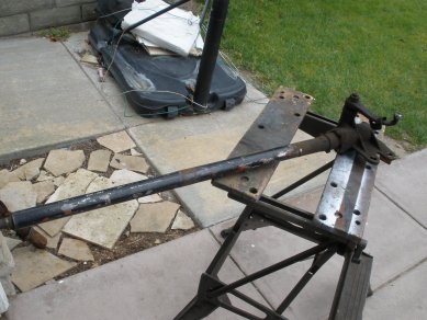
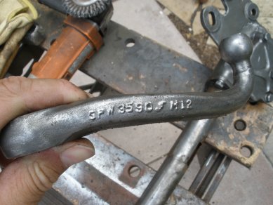
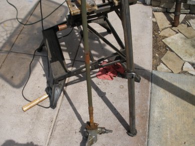
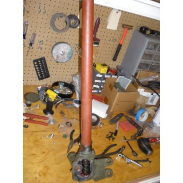
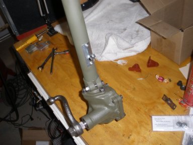
2. This steering was removed from a 1944 gpw. From the start we see the steering tub is bent, and by the looks of it, most likely will need some replacement parts. |
|
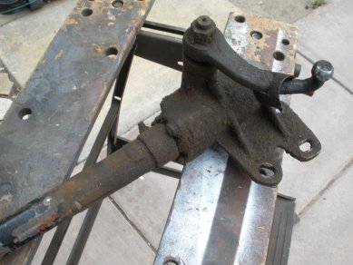
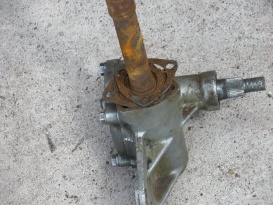
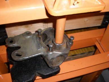
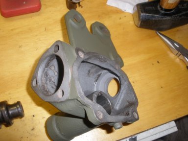
3. Most steering boxes on an Army Jeep project look like this…covered with years of grease, and signs of rust around it. |
|
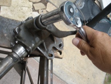
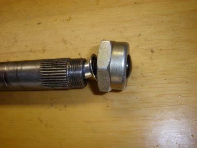
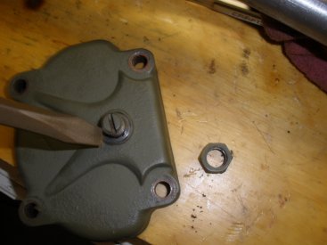
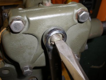
4. After knocking off most of the crud with a wire wheel on a grinder, we remove the Steering Gear arm nut. In order to clean further, we need to pull off the arm. |
|
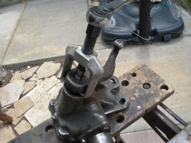
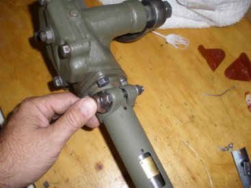
5. With an inexpensive puller, we pull the arm off. Note: don't try pounding this off as it will require a puller to do it correctly without damaging the arm. |
|
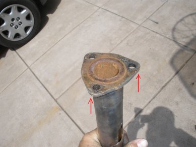
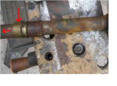
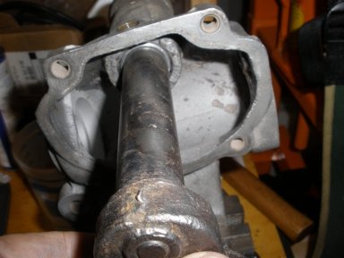
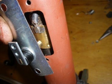
6. With the Steering gear arm off, we continue to wire wheel the steering column. Here you see the tube is cracked around the terminal for the horn connection. |
|
7. Ford Owners |
|
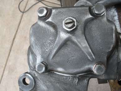
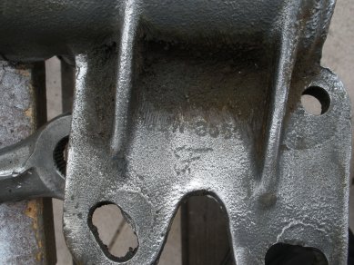
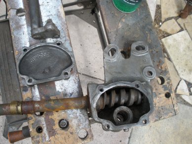
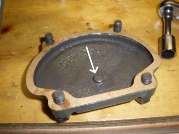
8. Here you see the side cover is cleaned off so we can prepare to remove it. Ford Owners Note the F mark on the side cover. |
|
9. Ford Owners |
|
10. Loosen the upper housing clamp and pull up the tube, then unscrew the 3 bolts holding the upper housing cover. You should be able to pull the tube up off the steering column. |
|
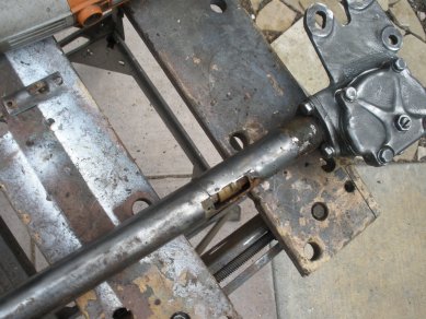
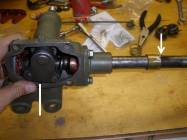
11. Here you see the steering tube and the steering column side by side. |
|
12. With a rubber hammer, tap the upper housing cover off the tube. This should separate easily. |
|
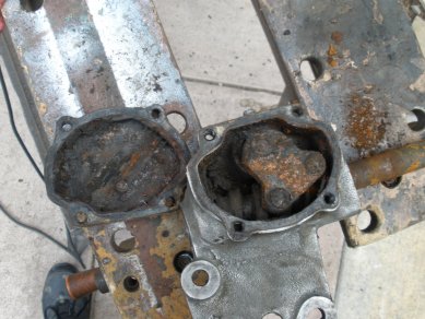
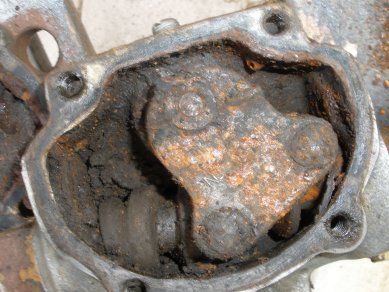
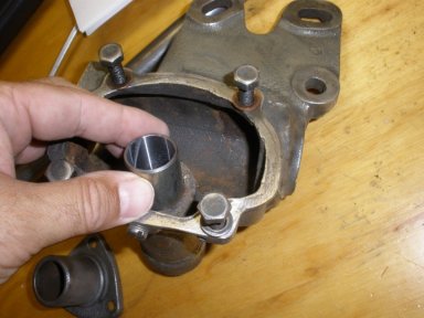
13. Now unscrew the 4 bolts on the side cover. With the side cover off inspect the inside of the steering housing. Here you can see there was not much maintenance done on this. |
|
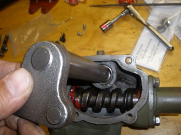
14. At a closer look inside the housing you see signs of rust around the lever shaft assembly. To clean out some of the crud, you should be able to turn your steering column and watch the lever shaft rotate. |
|
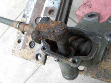
15. By rotating the steering column, you will see the lever shaft start to force itself upward. You can pull this out with your hand, or wedge a screwdriver in and finish bringing it out. |
|
16. Cleaning the parts up a little better, we now are ready to press the steering column out of the housing and blast all of the parts. |
|
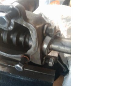
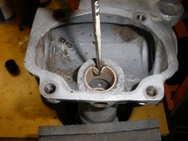
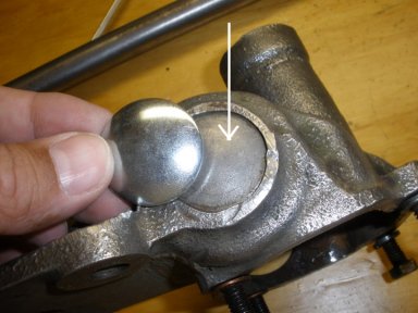
17. Next, to remove the shaft from the housing we spray penetrating oil around the upper cup and let it soak for a bit. By doing this, you can then give the shaft a good tug and the cup should pop right out. |
|
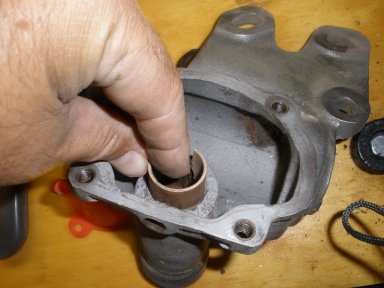
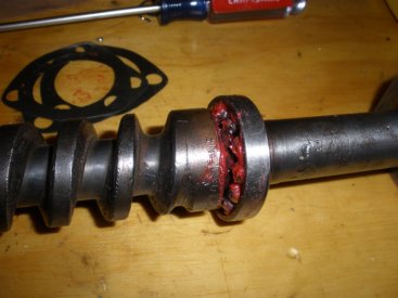
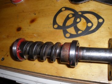
18. Remove the old contact bushing by soaking in penetrating oil, then tapping it off with screwdriver or chisel. After the bushing is off, Mark the position with a Felt Marker then take a wire wheel and clean the surface of the shaft and worm gear. |
|
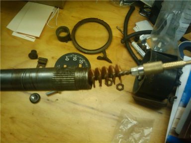
19. Next, check the inside of the shaft for rust. Here I used a 20 gauge gun cleaning brush and rod to clear out all the rust from the shaft. |
|
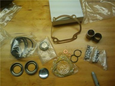
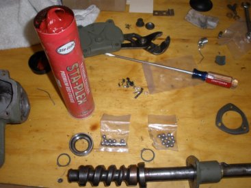
20. Here you see the gear box part kit, the horn wiring kit. This cost about $100 from Ron, but the steering is very important in your restore, so it is recommended to replace all these parts. |
|
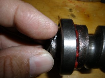
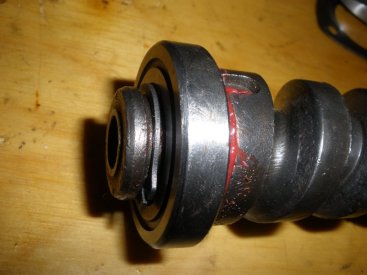
21. After we clean the shaft and it's worm gear, we will prepare to install the new cup, housing cover, and the contact bushing. First, install the cup on the shaft with the cup to hold the ball bearings toward the gears. The next step will be to install the contact bushing which requires some pounding, therefore, temporarily tape the cup at the bottom of the shaft near the gear. |
|
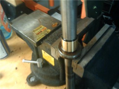
22. Next, to install the contact bushing you will need a soft piece of wood, a washer or the old cup. In a vise, we used the old cup, and sprayed WD40 on the shaft where the bushing is started. With the wood block at the top of the shaft gear, we start tapping the shaft downward. Because the inside piece is plastic, make sure you have plenty of lubrication in the process. Continue all the way down the shaft into position. |
|
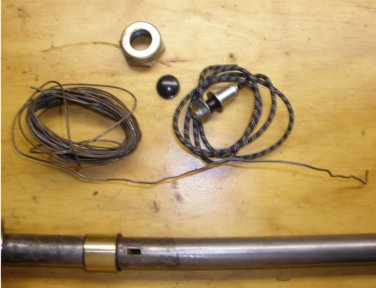
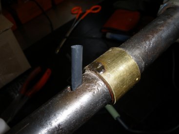
23. With the contact bushing down in place, lets prepare to install the wiring for the horn. Here you can see you will need some wire to pull it through. You might want to have your horn nut handy as well. You can install the top to keep the horn connector from catching on stuff prior to installing on your jeep. |
|
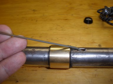
24. Run the wire down the steering shaft to top end. There we will hook it up and pull it back through. |
|
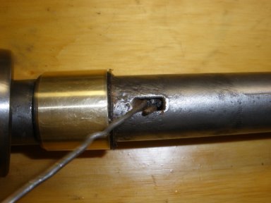
25. The hole your going to pull through in the shaft is just barely bigger than the wire, so this will be very tight when you pull it through. Here, you see to hook a very small piece of horn wire to your pull wire. |
|
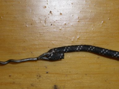
26. When you pull the wire back and you get to the opening in the shaft it is going to be very tight. You need to twist the pull wire while pulling about 90 degrees before the wire will fit through the opening. |
|
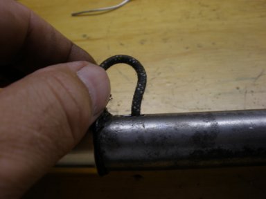
27. You want to pull the excess wire through with just a little extra at the top of the shaft. If you don't, you will have some back pressure from the wire when you try and apply the nut. |
|
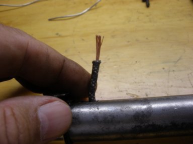
28. Prepare the wire to be soldered by cutting away about 1/4in of insulation. Place the wire over the bushing, and cut about 1/4 in below the bottom of the bushing. Then strip the wire and prepare for soldering. |
|
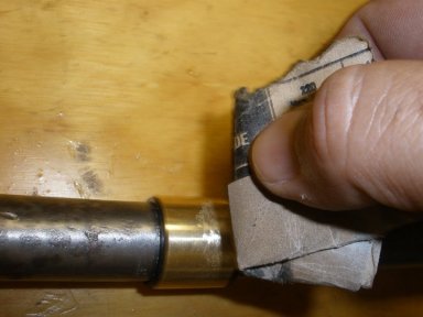
29. Next prepare the soldering area on the bushing by sanding the section that you will solder on. Note: the top of the bushing is where the contact will ride on the bushing from the steering column. |
|
30. *optional* here we put a little extra protection on the wire with a little heat shrink wrap. When the wire is being moved around with steering, this will protect it around the hole it comes through. In addition, we prep the bushing with a little solder prior to bringing the wire down. |
|
31. *check* make sure you have your top CUP and HOUSING TOP COVER (and shims) prior to soldering... make it a lot easier for fitting. Add Flux to surface area and wire prior to soldering otherwise solder will not stick. Place wire on copper bushing and solder on top of wire until it melts to bushing |
|
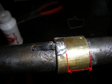
32. Solder is a nice fit with plenty of room for the brush to ride along the bottom half of the fitting. |
|
33. Temporarily install your horn nut and horn button on the top of the shaft; this will keep the horn wiring from catching on things as you work with the shaft. |
|
34. *back to the housing*. Now let’s remove the housing bushings. The TM's mention to use a chisel to pop the bushings out. In this case the copper bushings were very brittle and crumbled almost immediately upon impact. |
|
35. Once the bushings broke down a bit, they were easy to pull right out. |
|
36. Punch out the housing plug. Here you see it with the replacement plug. Turn the housing over and the plug will punch right out. |
|
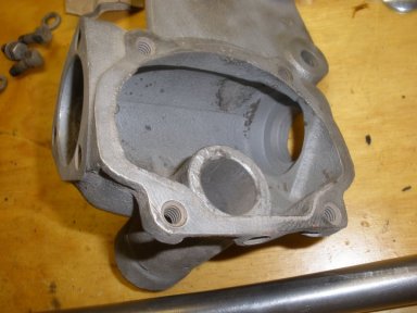
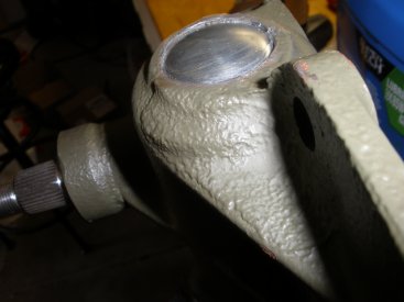
37. Blast the housing and clean out all the area where the new cups and bushings will be replaced. |
|
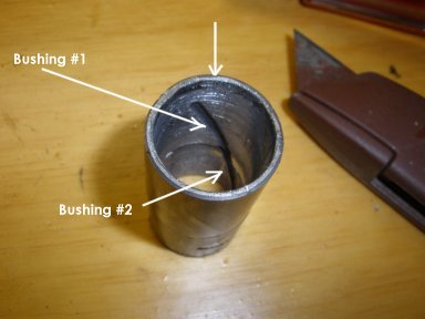
38. Take a look at your replacement bushings. From the replacement kit, you will see the short and long bushing together. Observe the grove in the middle. This is for lubrication flow on the shaft. The longer bushing grove stops before the edge so that the lubrication does not make it to the seal and leak. |
|
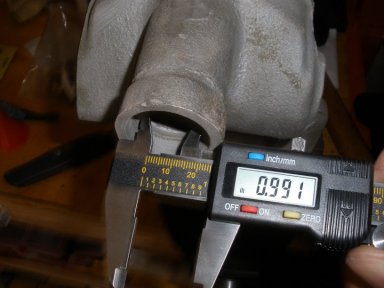
39. Prior to installing your replacement bushings, measure the inside diameter of the housing, and the outside diameter of the bushings. The bushings should fit tight, but the tighter they are, the smaller the inside diameter of the bushings will become when pressed in. |
|
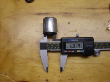
40. Measuring the inside diameter of the bushings will help you see how much the diameter will decrease when pressed in. |
|
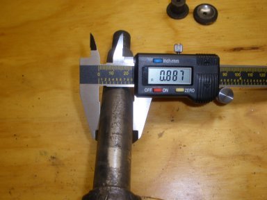
41. Last, measure the shaft as well. This should be within a .001 value to the inside diameter of the bushings. |
|
42. Next, line up the bushings to be pressed in. Here you see the bushing with the grove all the way to the end which will feed the lubrication to the shaft. You will want to line up the other bushing and press through the other side. |
|
43. Next, press the bushings into the housing. You should line up the grove on the bushings so that the lubrication will flow to the shaft |
|
44. After you have the bushings pressed in, test the fit with the shaft. Anticipate this being very tight. If it is to tight hone out the bushings a bit so that the shaft will fit and rotate firmly. |
|
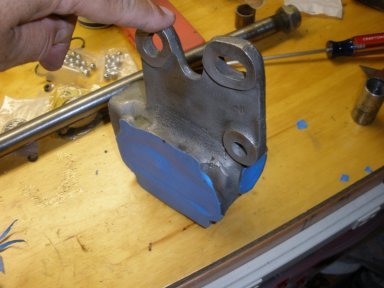
45. Next, prepare the housing for primer and paint. Everything else is assembly, so here lets paint in anticipation of finishing up the connections. |
|
46. Now that the housing is primed and painted you can start to assembly the rest of the housing. |
|
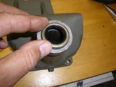
47. Here, install the housing seal by tapping it into the housing. It should be good and snug. |
|
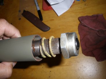
48. Now, prepare to install the main worm gear shaft. Here you see we will prepare with the new balls, rings, cups, and have some grease ready. |
|
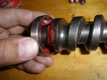
49. Start by installing the balls in the lower cup. Place some grease in the cup because the small ball bearings will slip out, and the grease will cause them to stick. Start with adding a couple balls, then press the cup on and put the rest of the balls in. |
|
50. Press one side of the ring around the ridge on the worm gear and press the ring around the ridge and it will snap into place. This side is the easier of the two. |
|
51. The lower side of the worm gear cup ring goes on pretty easy. You need to be careful with the ring as the resistance of the retainer ring will want to shoot out of your hands. |
|
52. Now grease the upper cup and place the balls in the cup. Again, put plenty of grease in the cup to help retain the balls in the cup. These little guys have minds of their own! |
|
53. The retainer ring on the upper side is a bear! You have to try and get it around the shaft and in its location without bending it all up. Here it was pressed around the shaft and placed into its location. |
|
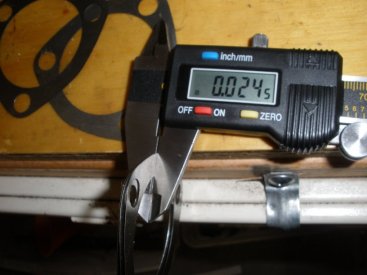
54. At this point you are ready to install the main shaft into the housing. Here I take out the shims and measure the .024 thickness that the TM suggests. when you install the shaft in the housing if it is loose (tugging up and down) then you have to many shims, if very tight in turning, then you don't have enough shims. |
|
55. Run your shims up on the main shaft, and push your worm gear into the housing. It should be a little snug, but will fall into the housing by a firm press into position. |
|
56. Now install your main shaft cover tightening the bolts down. When tightened, turn the main shaft and tug up and down. If you have play up and down, then you need to take a shim out, if turning is really tight, then add a shiim. In this case, it was a little loose with play in the top and bottom. |
|
57. In this case, I needed to reduce the shims down to two (from three) to get a snug fit. It was about .018 measurement. Repeat the steps to put back on and test. Ahh, much better. Turns well with no play. |
|
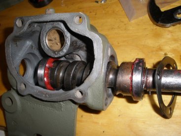
58. Install the main tube over the main shaft. Here, check two things. First the turning of the main shaft that there is no drag, and second look to see if you contact arear for the orn is linged up. Note the position of the contact area hole. Should be pointing upward for the connection to the horn after you install the steering. |
|
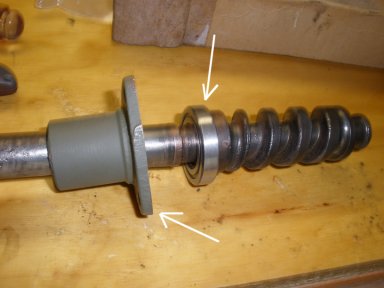
59. Here you see the contact will run on the bushing for the horn just fine. It lined up well and will not hit the soldering. |
|
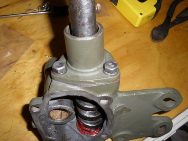
60. Next install the housing plug at the end of the housing. Clean your surface around this area and tap the plug into place. |
|
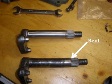
61. Here you see the old sector shaft was bent, so a replacement was required. It was not obvious when you looked at it, but when you put it in the housing and it hits a snag, it becomes obvious. |
|
62. Now, insert the new sector shaft into the housing with the new bushings. In this case, the fit was to tight for the second bushing, so we needed to hone it out a bit to get it to fit through. |
|
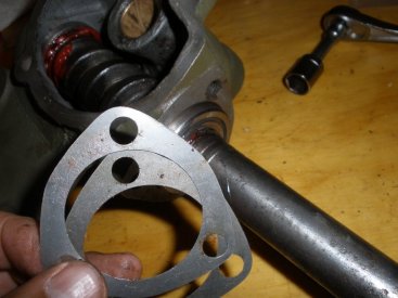
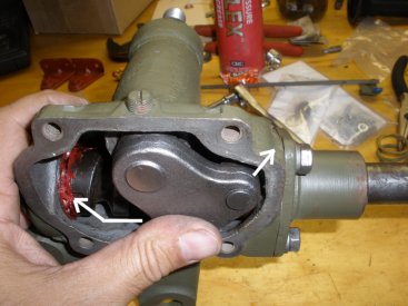
63. The sector shaft should push all the way through and line the teeth up on the worm shaft in the center. Here you see the contact ring is lined up in the middle of the shaft. If you have issues, you will want this lined up with straight wheels later. |
|
64. One the sector shaft is in, turn the main core shaft and feel the sector shaft fit with the worm gear and verify that it is lined up in the middle where the contact wire is facing upward as mentioned before. |
|
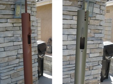
65. At this point, it is good to finish the painting of the main shaft tube. Primer and paint the tube and clamp as we are almost ready to install. |
|
66. Before you replace the cover plate on the housing, you want to loosen up the screw on the housing plate. This screw keeps the sector shaft from pushing itself out of position when the worm shaft is moving. If it is on to tight, the sector shaft will not move. |
|
67. The housing plate screw will allow the sector shaft to move back to a certain point in the housing. If you adjust this to far in, the shaft will become to tight, if it is to loose, the teeth may skip in the worm gear. |
|
68. With the cover bolted on, rotate the cover screw clockwise while turning the main shaft. Turn until you feel a slight drag on the sector shaft while turning. Back off just a bit, and tighten the nut around the cover plate screw. Test the main shaft moving from one end to the other. |
|
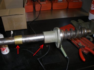
69. Now take the Shaft tubing and tighten it to the housing. Align the the contact bush opening with the top of the housing. If you don't it will be hard to reach when your wire up your tub. |
|
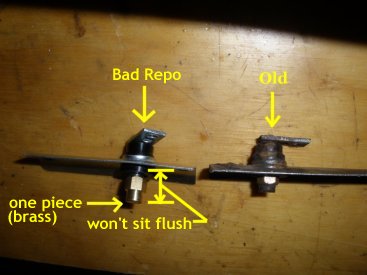
70. REPO Contact Brush (left) is a new repo, and (right) is the original. Couple problems with the new repo. 1) it does not seat flush, at least 1/8in off (requiring grinding down) 2) One piece, Brass will wear faster than a copper one. |
|
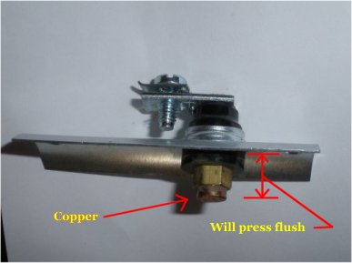
71. Tip: Buy a quality contact brush! Here you see a quality contact brush that will compress to be flush, and the contact area is copper (like the ring). The repo contract brush above is garbage compared to this one. |
|
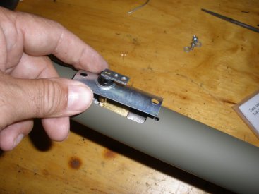
72. Now install the brush on the contact tube. Place the tube down the shaft and over the housing fitting, down as far as it will go and tighten up. |
|
73. Now install the steering wheel spring and the steering nut with horn button so that the wire and contact do not get bent up. |
|
74. Steering is rebuild is now complete and ready for install. Good exercise. This rebuild cost about $225 in parts, plus some donated NOS parts from Harley Padilla. Hope this helps! |
|
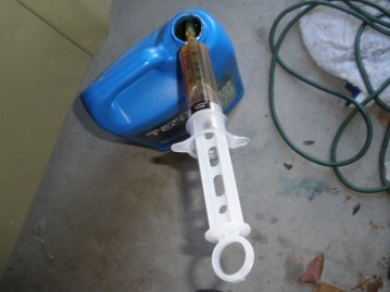
75. Now, use your SAE 90 wt oil and a device to pour into the top of the steering plug hole. Here you see a very inexpensive surenge that will allow us to insert the oil into the housing easily and without mess. |
|
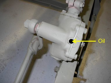
76. Once you install the Steering column on your frame, remove the plug and add your oil and fill the housing to the top. |

|
77. The Lubrication guide for your WWII jeep shows the steering box should contain oil. Many owners have moved to grease so the housing will not leak. Once the grease is displaced (with the high steering pressure) it will not return back, like oil does, so you are immediately left without lubrication thus parts will wear down rapidly. |

|
78. Special thanks to Horace Fenech for his advice and review of the article accuracy. And thanks again to Harley Padilla who donated his NOS parts for some inadequate repo parts. |